Solution · Data Centre

From plot to issued drawings.

Pick the site, set the rules — one engine generates a coordinated data centre from basement to terrace, then schedules, analyses, prices and draws it. No months of trade-by-trade coordination.

CFD thermal simulation of a data hall — hot and cold aisle airflow across rack rows and CRAH units
CFD · thermal map
ASHRAE A1 · PUE 1.40
Hot / cold aisle · 18–30 °C
Built for LivDES
Configured rule sets

Your standards, encoded once.

Pick the site, then let the engine apply your rule sets — planning, MEP, access & site — to generate a coordinated data centre from basement to terrace. Change a rule, the whole model re-resolves.

PLANNING
  • Server rooms & white space
  • Support spaces
MEP
  • Power
  • Cooling
  • Fire suppression
  • Network
ACCESS & SITE
  • Doors & openings
  • Parking & site features
One engine, end to end

From site to issued drawings.

One model carries the whole data centre — scroll the workflow.

MapLibre · OpenStreetMap
Search location…
Search
Site Selection
Land Area
1.14 hectares
(122,421 sq ft)
Adjacent Features
Roads
Buildings
Green Areas
Water
Railway
Reset
Edit
Confirm
Rule sets 3 groups · ready
PLANNING
Server rooms
Support spaces
MEP
Power
Cooling
Fire suppression
Network
ACCESS & SITE
Doors & openings
Parking & site
Generate layout
Basement → Terrace · 5 floors
Ground Basement 1st Floor Floor Plan
TR-1 32m² TR-2 32m² TR-3 32m² TR-4 BATTERY BMUS 100m² UPS AREA 125m² LV-1 LV-2 HVAC 3 risers FIRE PUMP SERVER HALL · WHITE SPACE R1 R2 R3 R4 R5 95 RACKS · HOT/COLD CONTAINED N 0 20m
Racks
Busway
CHW
5 trades · 0 clashes · 95 racks · 2.8 MW
NE SE SW NW 160% Basement
▾ Layers
Structural27
Electrical86
Mechanical32
HVAC8
A  Labels38
DG 1 DG 2 DG 3 DG 4 DG 5 DG 6 DG 7 DG 8 DG 9 DG 10 DG 11 DG 12 DG 13 DG 14 Power Riser 1 Fuel Storage AHU Plant Room Chilled Water Plant
38 rooms · 85 equipment · 30 duct runs 6/6 layers
All cooling fire it network power support 2,123 items
# Room Type Label Rating kW Manufacturer Model
1 Server Room (GF) Rack 42U rack 7.5 APC NetShelter SX
2 Chilled Water Plant Chiller Chiller 1 Trane CVHF 800T
3 Power / Utility Panel Switchgear MSB-A Schneider LV Switchgear
4 DG 1 (Basement) Generator DG Set A 1800 Cummins 2000 kVA
5 Fire Pump Room Pump Jockey Pump Grundfos Hydro MPC
6 AHU Plant Room AHU AHU-03 Daikin Modular AHU
7 IT / NOC Office Switch Core SW-1 Cisco Nexus 9000
8 Battery BMUS UPS UPS-GF-1 750 Vertiv Liebert EXL
Total: 2,123 items84,795.4 kW
TOTAL IT LOAD
7680.0 kW
FACILITY LOAD
10752.0 kW
COOLING
2550.0 tons
PUE
1.40 ratio
TIER
Tier III
power coolingredundancyenergycompliancecables 3 fixes available
SINGLE LINE DIAGRAM · 96 nodes
UTILITY
33kV A
33kV B
GEN
DG-1
DG-2
DG-3
ATS
ATS-A1
ATS-A2
ATS-B2
TRANSFORMER
TR1
TR2
TR3
SWITCHBOARD
MSB-A
MSB-B
SMDB-A
UPS
UPS-1
UPS-2
UPS-3
STS
STS-1
STS-2
STS-3
RACK
Row 1
Row 2
Row 3
Structural
$2.51M
Electrical
$17.68M
Mechanical
$1.79M
Fire
$0.82M
Network
$0.18M
Grand Total
$25.96M
#DescriptionUnitQtyUnit CostTotal
Structural (3 items)$2,507,340
1Raised access floorsqm6,720$120$806,400
2External wall constructionlm7,023$180$1,264,140
Electrical (9 items)$17,684,642
5Diesel generator setsnos28$324,000$9,072,000
7IT equipment racksnos1,536$3,500$5,376,000
10UPS unitsnos4$450,000$1,800,000
Mechanical (9 items)$1,786,791
13Chiller plant unitsnos4$239,864$959,454
14Computer room air handlersnos12$35,000$420,000
Generate Budget Export CSV
DRAWING TYPES
Floor Plan
Rooms, corridors, equipment
Power SLD
Single-line distribution
Cooling Schematic
CHW block diagram
Equipment Schedule
Tabulated list
A1 A2 A3 A4
Generate
Floor Plan — Ground FloorA31:100Download SVGPDFPrint
SERVER HALL · 95 RACKS · 2.8 MW DATACENTER MEP · GF · Rev 1
01 · SITE

Start with the real plot.

Pick the parcel on the map — LivDES reads the land area, roads, water, power and rail around it.

02 · RULE SETS

Your standards, encoded.

Planning, MEP and access rules drive every placement — server halls, power, cooling, fire, network, doors and parking.

03 · FLOOR PLAN

Basement to terrace, generated.

Every floor laid out and coordinated from the configured rules — rooms, equipment and routing in one model.

04 · 3D MODEL

See it before it is built.

Toggle floors and trades. Structural, electrical, mechanical and HVAC — all placed and labelled.

05 · SCHEDULES

Every asset, counted.

Cooling, fire, power and support equipment scheduled with ratings, weights and models — thousands of items, one list.

06 · ANALYSIS

Validated against load.

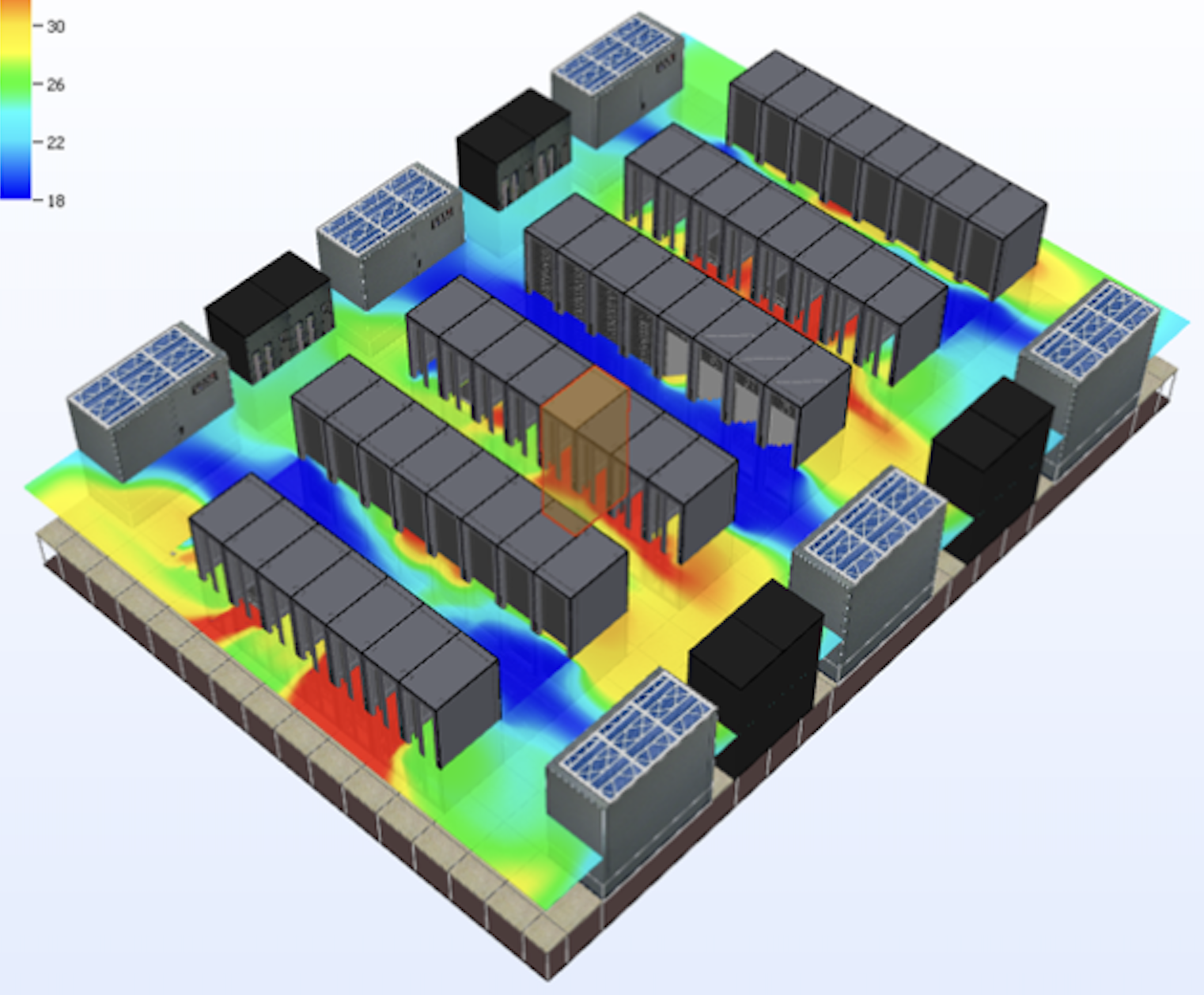
Power, cooling, redundancy, energy, compliance and cabling — checked, with fixes you can apply back to the design.

07 · BUDGET

Priced as you design.

A live BOQ across structural, electrical, mechanical, fire and network — to the line item.

08 · DRAWINGS

Issue-ready outputs.

Floor plans, power SLDs, cooling schematics and equipment schedules — exported to SVG or PDF.

From capacity plan
to clash-free model — on the call.

Bring the constraints. SAM brings the hall.